
#Meshlab stl to step install#
In the WelSim software, create a new FEM Project, and select Import Geometry from the menu or toolbar.Open the Terminal and run the following command: conda install -c open3d-admin open3d=0.8.0.0.Users can quickly complete the meshing projects by importing STL files, generate tetrahedral solid meshes (Tet4), and export FEA mesh files for subsequent finite element analysis.
#Meshlab stl to step software#
The general-purpose finite element software WelSim already supports the conversion of STL surface meshes into solid meshes for finite element analysis. Generally, the second-order element is better than the linear first-order element, but the increase in the number of nodes in the second-order element will also lead to a relatively expensive computation. The order of the element will also affect the results of the finite element analysis. The smaller the value, the more ideal the element is. Skewness: A measure of the regularity of an element. The ideal element has an aspect ratio of 1. The ideal value is 1, and it cannot be less than 0.Īspect ratio: refers to the ratio of the longest side to the shortest side of the element. Jacobian ratio: The ratio of the Jacobian matrix derived from the global and local coordinates. The commonly used quantities for mesh quality are:

Some topologically complex areas also require dense mesh. While the dense mesh leads to a heavy calculation burden. The coarse mesh results in accurate problems. This difference also makes the FEA solid mesh more complex than the surface mesh represented by STL, and the amount of data is also much vaster.įinite element mesh has relatively high requirements on the quality of the elements. The solid element not only has the overall surface information but also has discrete meshes inside. Commonly used solid elements are tetrahedral and hexahedral elements, which are widely used in 3D structural, thermal, fluid, acoustic, and electromagnetic simulations. However, 3D solid elements are the most widely used. 3D mesh in FEAĪlthough there are some special types of elements in 3D finite element analysis, such as surface elements representing plates and shells, and line elements representing truss and beams. We will describe them in future articles. In addition to OFF files, PLY (Standford triangle mesh), OBJ and other surface meshes also have some applications in industry and academia. They all start with OFF keywords and are easy to identify. OFF files are highly readable, the point set and face set is simple and clear. Unlike the STL file, the OFF file gives information about the number of vertices and the number of triangles and edges, but the OFF file does not indicate the normal vector of the triangles. At present, almost all 3D printers on the market perform printing by recognizing STL models.Īnother widely used triangle format is OFF (Object File Format). Because of the simplicity and not prone to errors, STL has become the most commonly used file format and the de facto interface standard in the field of rapid prototyping technology. Note that the topological relationship between the triangular faces is not given in the file, the triangles are adjacent through sharing two vertices. The definition of each triangular face includes the coordinates of vertex and the normal vector of the triangular face.
#Meshlab stl to step series#
The STL file is composed of a series of unordered triangular faces. It is a 3D graphics file format that serves rapid prototyping technology. The STL format (short for Stereo Lithography) is an interface protocol developed by 3D Systems in 1988. At the same time, different data storage formats have been developed, among which STL, OFF, OBJ, PLY, etc. Especially with the vigorous rise of 3D printing technology, the triangular surface mesh has become the focus of the 3D model representation method. With the rapid development of computer graphics, triangular mesh models have been widely applied in many fields such as 3D animation, e-commerce, computer-aided design, manufacturing, and digital entertainment. Due to the simple and quick processing of the triangular mesh, good visualization, and nice performance, it is regarded as one of the common methods to describe the 3D model.

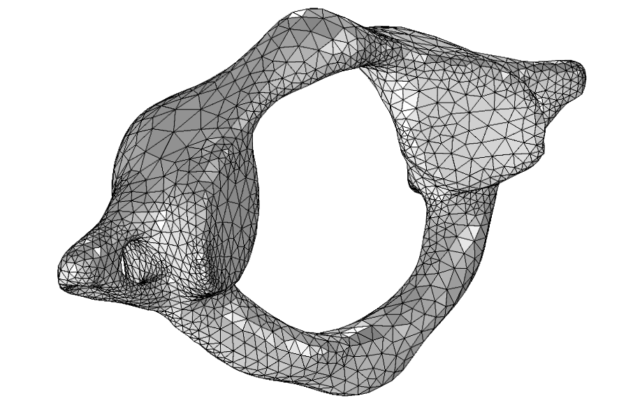
Using this primitive representation method, almost all 3D model surfaces can be approximated by using triangles. This approximation method is also used by most 3D mesh-based geometries. It uses points and edges to form many small spatial triangles to approximate the surface of a 3D model.

Triangular mesh refers to a surface model composed of triangular elements.


 0 kommentar(er)
